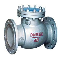
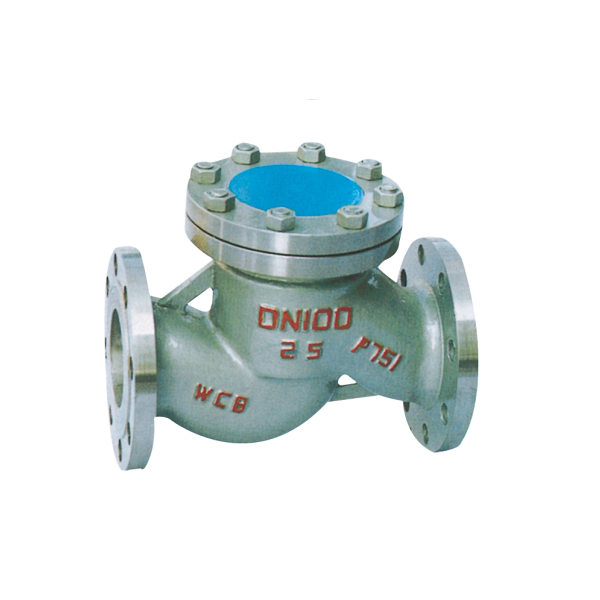
Lift check valve
- name: Lift check valve
- Type: H41
- Presure: 1.0~10MPa
- Specifications: DN15~DN500
- material: WCB CF8 CF3 CF8M CF3M

Product description
Lift check valves refers to relying on the media itself, the flow to automatically open and close the valve, by means of the valve clack gravity and fluid pressure automatically to prevent fluid backflow valve, also known as a non-return valve, a one-way valve, a reversing valve, and back pressure valve. Check valve is an automatic valve, its main role is to prevent the media back, to prevent the pump and drive motor reversal, as well as the release of the container medium. Check valve can also be used to give the pressure may rise to more than the system pressure of the auxiliary system to provide supply pipeline.
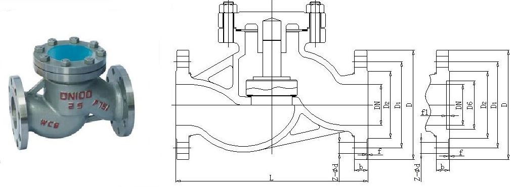
主要连接及外形尺寸(PN25)
公称通径
主要连接及外形尺寸
阀体连接尺寸
法兰连接尺寸
L
H
D
D1
D2
b
f
z-Φd
15
130
100
95
65
45
16
2
4-14
20
150
105
105
75
55
16
2
4-14
25
160
120
115
85
65
16
2
4-14
32
180
130
135
100
78
18
2
4-18
40
200
135
145
110
85
18
3
4-18
50
230
149
160
125
100
20
3
4-18
80
310
169
195
160
135
22
3
8-18
100
350
194
230
190
160
24
3
8-23
150
480
255
600
250
218
30
3
8-25
200
600
305
360
310
278
34
3
12-25
主要连接及外形尺寸(PN40)
公称通径
主要连接及外形尺寸
阀体连接尺寸
法兰连接尺寸
L
H
D
D1
D2
D6
b
f
f1
z-Φd
15
130
100
95
65
45
40
16
2
4
4-14
20
150
105
105
75
55
51
16
2
4
4-14
25
160
120
115
85
65
58
16
2
4
4-14
32
180
130
135
100
78
66
18
2
4
4-18
40
200
135
145
110
85
76
18
3
4
4-18
50
230
149
160
125
100
88
20
3
4
4-18
80
310
169
195
160
135
121
22
3
4
8-18
100
350
194
230
190
160
150
24
3
4.5
8-23
150
480
255
300
250
218
204
30
3
4.5
8-25
200
600
305
375
320
282
260
38
3
4.5
12-30
主要连接及外形尺寸(PN64)
公称通径
主要连接及外形尺寸
阀体连接尺寸
法兰连接尺寸
L
H
D
D1
D2
D6
b
f
f1
z-Φd
15
130
100
105
75
55
40
18
2
4
4-14
20
150
110
125
90
68
51
20
2
4
4-18
25
160
125
135
100
78
58
22
2
4
4-18
32
180
140
150
110
82
66
24
2
4
4-23
40
200
168
165
125
95
76
24
3
4
4-23
50
230
170
175
135
105
88
26
3
4
4-23
80
310
205
210
170
140
121
30
3
4
8-23
100
350
230
250
200
168
150
32
3
4.5
8-25
150
480
265
340
280
240
204
38
3
4.5
8-34
200
600
310
405
345
300
260
44
3
4.5
12-34
-
-
Main Parts material
Material code
Valve body, valve cover
Valve clack
Swing arm
shim
C
WCB carbon steel
WCB+hard alloy or stainless steel
WCB carbon steel
Graphite+304
P
CF8(304) stainless steel
stainless steel
CF8(304) stainless steel
PTFE
R
CF8M(316)stainless steel
stainless steel
CF8M(316)stainless steel
PTFE
I
WC6 Cr Mo steel
Alloy steel + hard alloy
WC6 Cr Mo steel
Graphite+304
V
WC9 Cr Mo steel
Alloy steel + hard alloy
WC9 Cr Mo steel
Graphite+304
Other special materials, our company can also be tailored to customer needs.
-
Shell material
Applicable medium
Applicable temperature(℃)
Carbon steel(C type)
Water, steam, oil
≤425
Cr.mo.ti steel(P type)
Nitric acid
≤150
Cr.ni.mo.ti steel(R type)
Acetic acid
≤150
Cr.mo. steel(I type)
Water, steam, oil
≤550
nominal diameter PN(MPa)
shell(MPa)
test pressure(MPa)
up seal(MPa)
seal(liquid)(MPa)
seal(gas)(MPa)
1.6
2.4
1.8
0.6
1.8
2.5
3.8
2.8
0.6
2.8
4
6
4.4
0.6
4.4
6.4
9.6
7
0.6
7
- Implementation standards:
Design standard: GB/T12235
Structure length: GB/T12221
Connecting flange: JB/T79, GB/T9113, HG/T20592, HG/T20615
Experiment and test: JB/T9092, GB/T13927
Pressure - temperature: GB/T9131
Product label: GB/T12220
- Storage and maintenance
1 the valve must be kept in a dry, ventilated room.
2 the storage period of the valve, the valve should be closed and fixed, both ends of the flange should be closed.
3 during the storage of the valve, the surface of the machine is easy to be removed.
4 long-term storage of the valve should be regularly checked, timely protection.
Installation and maintenance
1 the valve is installed in the horizontal pipeline
2 must be carefully checked before installation, the valve plate is marked and consistent with the requirement and condition.
3 when installing, should check the inner cavity, remove the valve flap fixing device, try to check the sealing surface of the valve flap, and clean.
4.. Lifting the valve before, should check whether it has been tightening screw ring.
5 installation should pay special attention to media flow, should make the normal flow direction of the media and the direction of the arrow on the valve body consistent.
6 when installing, tighten the connecting bolts evenly and symmetrically.