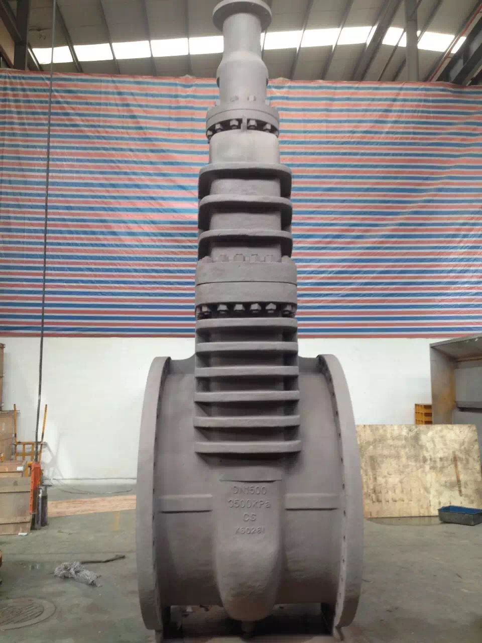
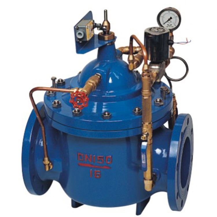
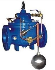
100D constant water level valve
- name: 100D constant water level valve
- Type: 100D
- Presure: 1.0~2.5MPa
- Specifications: DN50~DN600
- material: Grey cast iron, nodular cast iron, carbon steel

Product description
100D water valve is a valve diaphragm type adjustment tank and water tower in height. The valve is controlled by the floating ball, when the liquid level reaches the set height, the valve passes the signal through the relevant structure to transfer a water pump, and the water pump stops the water supply; when the liquid level bottom is in the set position, the water pump automatically supply water. The valve action is stable and effective to prevent the opening of the pump water hammer and stop pump water hammer. Avoid excessive pressure on the pipe. Automatic water supply system for water tank, a water tower. The valve maintenance is simple, flexible and durable, high accuracy of level control, the water level is not affected by water pressure interference and close tight, reliable performance.
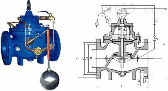
Main connection and dimensions(PN10)
公称
通径
主要外形尺寸及连接尺寸(mm)
阀门尺寸mm
法兰连接尺寸mm
L
H1
H
D
D1
D2
b
f
Z-Φd
50
203
210
265
165
125
93
18
3
4-Φ18
65
213
215
310
185
145
113
18
3
4-Φ18
80
241
245
350
200
160
128
20
3
8-Φ18
100
272
305
460
220
180
148
20
3
8-Φ18
125
300
365
520
250
210
178
22
3
8-Φ18
150
333
415
570
285
240
204
22
3
8-Φ22
200
400
510
595
340
295
259
24
3
8-Φ22
250
480
560
780
395
350
314
26
3
12-Φ22
300
550
658
905
445
400
362
26
4
12-Φ22
350
620
696
1025
505
460
422
26
4
16-Φ22
400
685
735
1030
565
515
473
26
4
16-Φ26
450
750
610
1080
615
565
523
28
4
20-Φ26
500
810
665
1135
670
620
578
28
4
20-Φ26
600
935
725
1270
780
725
677
34
5
20-Φ30
主要连接及外形尺寸(PN16)
公称
通径
主要外形尺寸及连接尺寸(mm)
阀门尺寸mm
法兰连接尺寸mm
L
H1
H
D
D1
D2
b
f
Z-Φd
50
203
210
265
165
125
93
18
3
4-Φ18
65
213
215
310
185
145
113
18
3
4-Φ18
80
241
245
350
200
160
128
20
3
8-Φ18
100
272
305
460
220
180
148
20
3
8-Φ18
125
300
365
520
250
210
178
22
3
8-Φ18
150
333
415
570
285
240
204
22
3
8-Φ22
200
400
510
595
340
295
259
24
3
12-Φ22
250
480
560
780
405
355
315
26
3
12-Φ26
300
550
658
905
460
410
370
28
3
12-Φ26
350
620
696
1025
520
470
428
30
4
16-Φ26
400
685
735
1030
580
525
479
32
4
16-Φ30
450
750
610
1080
640
585
539
40
4
20-Φ30
500
810
665
1135
715
650
601
44
4
20-Φ33
600
935
725
1270
840
770
716
54
5
20-Φ36
主要连接及外形尺寸(PN25)
公称
通径
主要外形尺寸及连接尺寸(mm)
阀门尺寸mm
法兰连接尺寸mm
L
H
H1
D
D1
D2
b
f
Z-Φd
50
203
210
265
165
125
93
20
3
4-Φ18
65
213
215
310
185
145
113
22
3
8-Φ18
80
241
245
350
200
160
128
24
3
8-Φ18
100
272
305
460
235
190
154
24
3
8-Φ22
125
300
365
520
270
220
180
26
3
8-Φ26
150
333
415
570
300
250
210
28
3
8-Φ26
200
400
510
595
360
310
270
30
3
12-Φ26
250
480
560
780
425
370
326
32
3
12-Φ30
300
550
658
905
485
430
386
34
3
16-Φ30
350
620
696
1025
555
490
441
38
4
16-Φ33
400
685
735
1030
620
550
498
40
4
16-Φ36
450
750
610
1080
670
600
548
46
4
20-Φ36
500
810
665
1135
730
660
608
48
4
20-Φ36
600
935
725
1270
845
770
713
58
5
20-Φ39
Main parts material
Material code
Valve body, valve cover
The stem
valve seat
sealing ring
diaphragm
spring
Z
HT200 Gray cast iron
20Cr13
Gray cast iron
NR/NBR/EPDM/FEP/PFA
NR/NBR/EPDM/FEP/PFA
stainless steel
Q
QT450 Nodular graphite cast iron
20Cr13
Nodular graphite cast iron
C
WCB carbon steel
20Cr13
carbon steel
Other special materials, our company can also be tailored to customer needs.
Main performance characteristics
Shell material
Shell applicable temperature(℃)
Casing applicable pressure MPa
Gray cast iron(Z type)
≤200
≤1.6
Nodular graphite cast iron(Q type)
≤350
≤4.0
carbon steel(C type)
≤425
-
stainless steel(R type)
≤650
-
Sealing ring / diaphragm
Applicable medium
Applicable temperature(℃)
Natural rubber (NR)
ydrochloric acid, 30% sulfuric acid, 50% hydrofluoric acid, alkali, etc. 50%
≤85
Nitrile rubber(NBR)
Water, oil, waste gas and waste liquid pollution.
≤150
Ethylene propylene rubber (FPDM)
In addition to salt water, 40% boron water, 5%~15% nitric acid and sodium hydroxide, etc..
≤120
Poly (ethylene propylene) plastics(FEP)
In addition to the molten alkali metals, fluorine and aromatic hydrocarbons hydrochloric acid, sulfuric acid, aqua regia, organic acid, strong oxidizing agents, concentrated and dilute acid alternate, alternating alkaline and various organic solvents.
≤150
Fusible polytetrafluoroethylene (PFA)
≤180
Nominal pressure PN(MPa)
Shell(MPa)
Test pressure(MPa)
Seal (liquid)
Seal (gas)
1.0
1.5
1.1
0.6
1.6
2.4
1.76
0.6
2.5
3.75
2.75
0.6
- Implementation standards
Design specification: JB/T10674
Structure length: JB/T10674, GB/T 12221
Connecting flange: GB/T9113, HG/T20592, HG/T20615, JB/T 79
Experiment and test: GB/T13927, JB/T 9092
Pressure temperature: GB/T 17241.7, GB/T12224
Product identification: GB/T 12220
- Valve maintenance
(1) the engineering application of the hydraulic control valve is a manufacturing plant inspection, a variety of complete, technical information to meet the requirements of the product.
(2) the nominal pressure of the valve has different levels, the pipeline transportation of the media, the working pressure should be less than the value of the valve nominal pressure.
(3) the project of the hydraulic control valve setting should have enough space for management, operation, installation and maintenance, and should meet the requirements of the pipeline valve.
(4) when the pipe is connected by flange, the hydraulic control valve with flange connection should be adopted, and the hydraulic control valve with groove connection should be adopted when the pipeline is connected with a groove.
(5) the hydraulic control valve should be set on the one-way flow of media in the pipeline.
(6) the direction of the arrow on the main body of the hydraulic control valve must be consistent with the direction of the pipeline system.
(7) the water control valve should not have gas blocking, air resistance. Automatic exhaust valve should be set at the highest position of the pipe network.
(8) when the valve is installed, the valve cover and valve stem should be facing up. Vertical installation, valve cover, valve stem should be outward.
(9) the valve should be done before the installation of strength and tightness test.